EHV lines operates in grid. We can understand
the changes in protection system when EHV feeders operates either in parallel
or grid with the help of following example.
Consider a part of the 132kV power system
as shown above. Here sub-station A is source sub-station and a 132kV double
circuit line is feeding the radial sub-station B. The double circuit line under
consideration is being protected by four circuit breakers controlled by four
over current relays R1, R2, R3 and R4 as shown above. Upon observing the
circuit and with common logic we can guess that time of operation for relays
will be as below-
1. R1 - 500 ms, R2 - 500
ms
2. R3 - 300 ms, R4 - 300
ms
Now let the fault on circuit-I as shown
in the figure. For this fault both relays R3 and R4 at Bus-B will experience
the same fault current and as we have to set its time of operation same both
will operate simultaneously. Thus selective tripping of only faulty circuit
will not be possible.
This difficulty can be overcome if only
relay R3 responses for the shown fault of Circuit-I. As seen from the diagram
this discrimination can be done by sensing the direction of power flow through
the circuit controlled by respective relay. We can see that relay R3 is
experiencing fault in forward direction (as it is protecting the Ckt-I) while
relay R4 experiences the fault in reverse direction. To have selective tripping
of the faulty circuit; only the relay experiencing fault in forward direction
shall responds to fault and operates the breaker.
This
type of relaying scheme is shown here by
adopting direction arrow convention. However at EHV level it is not necessary
to represent directional relay explicitly by arrow symbol as shown here because
all relays used in protection of EHV network are directional only.
Basics of Direction Sensing
In above examples we have mentioned that
the fault is in forward direction with respect to relay R3. Here we
have decided this by observing the position of the relay with
respect to fault and source. However in actual practice relay has to discriminate
between forward and reverse direction fault. How this can be achieved is
discussed in next sections.
Direction of AC current flow.
The
name “alternating current” suggests that there is no specified physical
direction of current flow. To elaborate this let us compare measurement of
alternating current and direct current by clip on meter as shown in following
figures.
DC
clip on meter has either arrow marking or polarity marking on jaw of the meter.
If the direction of current flow is reverse with respect to this marking it is
indicated by –Ve sign by clip on meter display. Thus current flowing from A to
B displayed as 17.32 A and it is -17.32
A if flowing from B to A.
However
for AC tong tester there is neither such marking nor any –Ve sign for displayed
current. Whether current flowing from A to B or B to A display will be +Ve
only.
Though
the change in direction of current flow in case of A.C. system does not changes
sign for clip on meter display still it is wide practice to show currents in
A.C system by direction. Obviously then someone may ask the question that; what
is the meaning of showing the direction of current flow in AC system?; and
answer to this is; it is actually direction of active power flow. Obviously
to determine power flow in circuit we require current as well as voltage. How
this is achieved is explained in next section.
Direction of power flow
As
mentioned in previous section to determine physical direction of current flow
(power flow) we require additional quantity; this additional quantity is
voltages causing current (respective phase voltage). The meaning of direction of AC current flow (power flow) can be
best understood with the help of power system as shown in figure.
As shown here consider a SLD for three
bus power system feeding the lagging power factor load. Let direction sensing
devices DA and DC are connected to Line-AB and Line-BC at
Bus-B. Bus-B CT and PT connections
are shown in the figure as per common
conventions listed below.
1) Connect PT secondary terminal “a” to device and “n” to earth
2) CT shall be installed such that its primary P1 terminal shall be
towards Bus
3) Connect CT secondary terminal S1 to relay and S2 to earth (with
other phase CT S2 terminal)
Let us consider an instance where Bus-A
is positive. Thus as per CT polarity the current flowing through CT primary and
secondary has the directions as shown in the figure.
Now as seen from the figure direction of
instantaneous current and voltage for device DC is same
(conventionally both entering into the device). Thus current phasor shown
lagging behind voltage phasor by the power factor angle of the load.
While for device DA direction
of instantaneous current and voltage is opposite (conventionally current is
leaving the device while voltage is entering into the device). Thus here
current phasor is reversed.
By observing the vector representation of
voltage and current in the figure (as shown below respective device) we can
easily conclude that; if standard connection convention followed then-
Whenever
angle between voltage and current is less than 900 (lagging or
leading) physically direction of power (current) flow is away from bus.
AND
Whenever
angle between voltage and current is more than 900 (lagging or
leading) physically direction of power (current) flow is towards bus.
Maximum Torque Angle
The word Maximum Torque Angle has its
roots in use of electromagnetic relays. In previous section direction sensing
explained by considering generic devices DA and DC.
Historically these devices were electromagnetic devices; where torque get
developed as a result of tow magnetic fluxes developed by tow electrical
quantities displaced by certain angle. Depending upon the direction of torque
produced direction of power (current) can be decided.
When two magnetic fluxes are derived from
two different electrical quantities the torque produced by these fluxes will
depend upon phasor relationship of these two quantities. Obviously for energy
meter and Watt Meter; for correct functioning of the devices; torque will be
maximum when applied voltage and current are in phase; while for VAR meter for
capacitor it would be maximum if current leads voltage by 900 and
for VAR meter for reactor it would be maximum if current lags voltage by 900.
This angle of applied current with
respect to applied voltage at which maximum torque get produced is called as
Maximum Torque Angle.
However situation explained above
entirely changes in case of a device which can discriminate direction of
current in case of fault (Directional Overcurrent Relay) due to following two
reasons
1) The voltage of faulty phase decreases drastically
2) Angle between voltage and current of faulty phase is nearly 900
Hence
direction decision making in case of fault becomes very difficult. How to
overcome these difficulties depends upon type of fault. There are mainly two
types of fault in electrical system a) Line-Line fault and b) Line-Ground
fault. Direction decision making philosophy and thus requirement of MTA
(Maximum Torque Angle) in case of each type of fault is entirely different and
we will discuss it in next section.
NOTE:
Now a days use of numerical relays become very common; where direction decision
making done numerically; by sampling voltage and currents many times during
each cycle and by using proper algorithm. However use of the word Maximum
Torque Angle carried forward as it is by most of the relay manufacturer. Some
relay manufacturer uses RCA (Relay Characteristic Angle) instead of MTA due to
this technological change.
MTA
for Line-Line Fault
Consider a part of the power system as
shown in the figure. Let there be Line-Line fault at point A and let direction
decision to be made by the relay at point B.
When
there is no fault; vector diagram representing voltage and current is as shown
in figure.
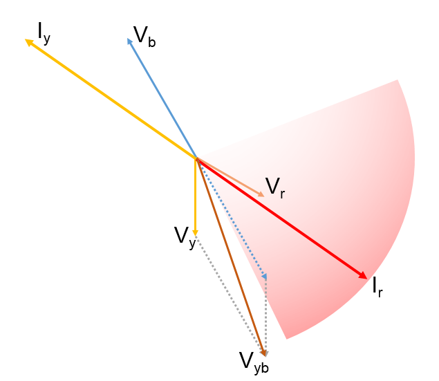
For
R-Y fault R-Ph and Y-Ph source voltage will decrease and will approach close to
each other and R-Ph current will lag approximately 900 with respect
to R-Y Phase voltage thus during fault vector diagram will be as shown in
figure.
Thus
depending up on nature of load and fault impedance R-Phase current may be
anywhere as shown by shaded area for figure.
Obviously voltage selected for this
direction decision making will be of healthy phases. That means if we are
considering direction decision making in respect of R-Ph current then we have
to choose VYB voltage as our reference voltage as shown in figure.
To include all this probable area for
R-Ph current it is necessary to redefine zone of forward direction with respect
to polarizing voltage VYB. Thus line AB is selected as new dividing
line for operating direction (Forward) and Non-Operating direction (Reverse).
Perpendicular line to this dividing line is line C-D. Now we can see that line
CD leads VYB. For electromagnetic relays this angle use to be 450.
Now for numerical relay this angle is settable still recommended value is +450.
MTA
for Line-Ground Fault
Consider R-Ph to ground
fault. During this fault R-Ph voltage will decrease and R-Ph current will be
lagging to R-Ph voltage nearly by 900 as shown in the figure-1.
However
Earth fault relay current In will be 1800 out of phase
with respect to R-Ph current as shown in figure-2
Thus depending up on fault impedance
R-Phase current may be anywhere as shown by red shaded area and thus
corresponding earth fault relay current may be anywhere as shown by green
shaded area for figure-3.
As
there may be the fault on any phase and as during fault; volatge of faulty
phase reduces nearly to zero it is not desirable to consider volatge of faulty
phase for deciding the direction of fault current. It is obvious choice to use
residual voltage V0 (vector sum of Vr, Vy and Vb) for deciding the
direction of fault current as shown in the figure.
To include all this probable area for
earth fault current it is necessary to redefine zone of forward direction with
respect to polarizing voltage V0. Thus line AB is selected as new
dividing line for operating direction (Forward) and Non-Operating direction
(Reverse). Perpendicular line to this dividing line is line C-D. Now we can see
that line CD lags V0. For electromagnetic relays this angle use to
be -450. Now for numerical relay this angle is settable still
recommended value is -450.

Conclusion
For protection of EHV lines generally
directional overcurrent and earth fault relays are used. In case of directional
relay it is necessary to set correct MTA for over current as well as earth
fault relay. Maximum Torque Angle depends upon factors such as source impedance
and method adopted for earthing of generators and transformers. In transmission
system generally solidly earthed transformers are used. Hence it is common to
use following settings for MTAa. For Overcurrent Relay MTA = +450 or 450
leading
b. For Earth Fault Relay MTA = -450 or 450
lagging