Whether you noticed that CT
connection to energy meter in S/S are such that we connect S1 to “OUT” terminal
of the meter instead of “IN”. Have you noticed that sign convention for import
and export of MW and MVAR being reported to LD from EHV S/S are reverse as
compared to that used at EHV consumer end? Have you faced difficulties about
polarity while doing connection of CT wire to MFM or ABT meter? Then this
explanation may help you.
Consider a SLD of small power system
as shown in figure-1 having three busses, a source and an inductive load. This
SLD also shows CT and PT connected to Bus-B along with primary and secondary
terminal identification for polarity.
Consider +Ve half cycle of the
voltage. Corresponding to this cycle conventional direction of current shown
through line AB and BC.
Accordingly secondary currents also
shown for devices DC. From the diagram we can observe that whenever
voltage is entering (?) in device Dc; current is also entering. Thus for device
Dc and for pure resistive load voltage and current will be in phase. Obviously
when load is inductive current will lag by some angle as shown in vector
diagram for device Dc.
From the above figure-1 we can conclude that
when active power is exported from bus; angle between voltage at that bus and
current is - 900 to + 900 and when active power being imported this
angle will be more than + 900 or less than - 900.
Furthermore we know the formula for calculating
power as complex number (like a + Jb) is as below
S = V.I*
Where S is complex power V is
voltage vector represented as complex number and I* is complex conjugate of
current. Using this formula we will calculate complex power for supply voltage
of 220kV and current of 400Ampere for different angle and tabulate the result
for ready reference.
From above table we can conclude that
theoretically for export from bus MW is +Ve and for import to the bus MW is
–Ve.
According to this theory if energy
meter is connected at consumer end with CONSUMER VIRTUAL BUS as reference (CT
P1 is towards consumer); the energy meter will record –Ve for power being
consumed. This –Ve recording for power consumption does not seems normal. Hence
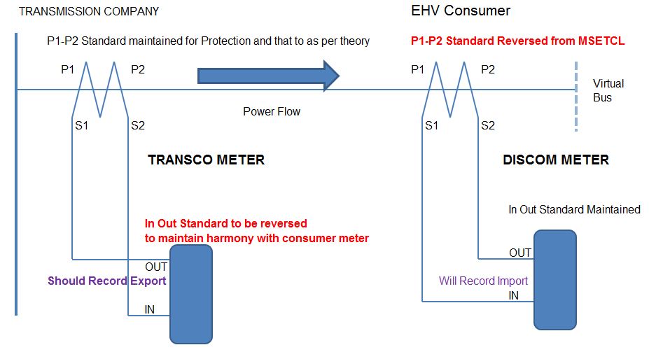
it is general practice to reverse P1 and P2 of CT at EHV consumer end (P1
towards grid supply and P2 towards consumer) as shown in Figure-2; to have
understandable sign convention; (+Ve) for power being consumed.
For EHV S/S as per connection
convention shown in Figure-1 and calculations with this convention (Table-1)
this export power will be +Ve. Hence to match with consumer end power; EHV S/S
end power to be recorded as –Ve and NECESSARY to call it is EXPORT. To happen
this we have to REVERSE the CT connections to meter at EHV bus as shown in
Figure-2.
Thus considering transmission
network bus as reference Export power (active and reactive) becomes –Ve and
Import power becomes +Ve. With this convention Table-2 with LD convention is
displayed as below.
Energy meter quadrants for MW and MVAR
recording AT CONSUMER END are as shown below for reference
From EHV S/S point of view
conventions of +Ve and –Ve will reverse i.e. Q1-VI quadrant will be Q3-VI
quadrant and Q2-VI quadrant will be Q4-VI quadrant.


This article is very helpful for understanding the concept of sign convention for energy meter. Now I got the basic reason for reversing the IN OUT standard, that is to maintain the harmony with consumer meter.
ReplyDelete